The content linked on this page refers to the journal paper, "Image-based registration for synthetic aperture holography", Opt. Express 19, 11716-11731 (2011).
An illumination field is incident on a diffuse object confined in a field of view (FOV) and creates a field scattered off the object. The incident field and the object field are denoted by Ei(x, y) and Eo(x, y), respectively. A point source is located below the object to create a reference field R(x, y). The object field Eo(x, y) propagates to the detector plane and creates a field Es(u, v; zd) incident on focal plane array (FPA). Also, the reference field R(x, y) propagates to the detector plane and creates a propagated reference field R(u, v; zr).

Figure shows the flow chart of estimation processes for image-based synthetic aperture holography. The estimation processes go through piston phase compensation, hologram block synthesis, WA hologram synthesis, and reference field estimation. The estimated errors are denoted in the processes.

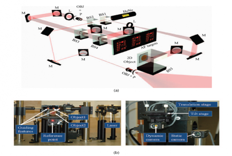
We designed our experiment to demonstrate coherent aperture synthesis in digital holography. The optical setup is composed of field generation and detection in Figure.A HeNe laser with the wavelength of 633nm and the power of 20 mW was used to make a monochromatic light source for hologram measurement. In the reference beam, the two mirrors were used to step down the reference beam maintaining laser polarization perpendicular to the optical table. The high NA microscopic objective lens generates a wide spherical field in the detector plane. Note the center of the reference field was vertically 100 mm lower than the center of the guiding features and axially 2.032 m (within +/-2 mm accuracy) away from the surface of FPA. Therefore, the generated object and reference fields interfere, forming a hologram field in the detector plane.

Figure shows the evolution of image resolution to the number of hologram patches in the estimated guiding features. The image of the 1 by 1 hologram patch barely resolves any feature (Group 2 and 3) in Figure (a) and (d). The image of the 3 by 3 hologram patches resolves the features (group 2, element 1) whose resolution corresponds to the theoretical resolution of 250 micron in Figure (b) and (e). The image of the 12 by 12 hologram patch resolves the features (group 4, element 1) whose resolution corresponds to the theoretical resolution 62.5 micron in Figure (c) and (f). Here we used the speckle-affected resolution.

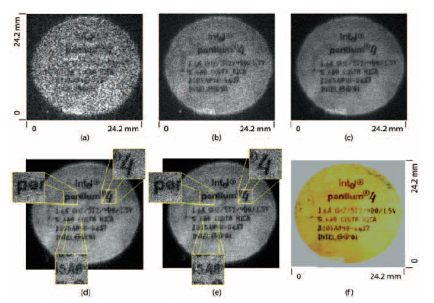
Figure shows the feasibility of depth imaging. The logo inscription of a CPU chip is in focus by backpropagating the estimated synthetic aperture hologram. The resolution improvement to the number of hologram patches is presented in Figure (a), (b), and (c). The more hologram patches we synthesize, the smaller letters are readable. Figure (d) and (e) show the effect of error estimation on the in-focus image. The zoomed-in images have better sharpness in the estimated image in Figure (e). Figure (f) shows an incoherent base line image of the logo inscription.

To process the WA hologram data, Dell Precision T5500 with specification of Intel Xeon CPU at 2.27 GHz and 48 GB RAM was used in 64 bit operating system